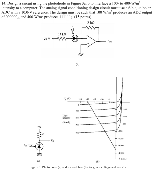
14 Design a circuit using the photodiode in Figure Circuit Diagram Photovoltaic mode: The circuit is held at zero volts across the photodiode, since point A is held at the same potential as point B by the operational amplifier. This eliminates the possibility of dark current. Photoconductive mode: The photodiode is reversed biased, thus improving the bandwidth while lowering the junction capacitance.
I'm trying to design a circuit to measure the ambient visible light (380nm to 750nm). Accuracy isn't too important. I've been looking at photodiodes, but I'm not sure how to connect them up. I need the following requirements from my circuit: low power; low accuracy; low cost photodiode (e.g. this on digikey) AD convert signal for uC
How to Use Photodiodes and Phototransistors Most Effectively Circuit Diagram
Arduino Photodiode Circuit Wiring. The wiring diagram for this example project is shown in the previous section, scroll up and check it out. Below is an image of how the whole setup looks like at the end, ready for the test. Arduino Photodiode Light Sensor Circuit #1. Arduino Photodiode Light Sensor OpAmp Circuit #2. Code Example

In nearly all cases, the photodiode must be used with an associated amplifier, such as a transimpedance amplifier (TIA) to convert the current flow into a useful signal. Figure 1: Due to the need for a lens and optical path to the sensor die, photodiodes and phototransistors require packaging which differs from conventional diodes and transistors. This circuit is designed to detect light levels using a photodiode and control an LED based on the detected light. The Arduino UNO reads the voltage across the photodiode connected to its analog pin A0 and turns on the LED connected to digital pin D3 through a 220 Ohm resistor if the light level falls below a predefined threshold.

Photodiode : Working and how to use in circuits Circuit Diagram
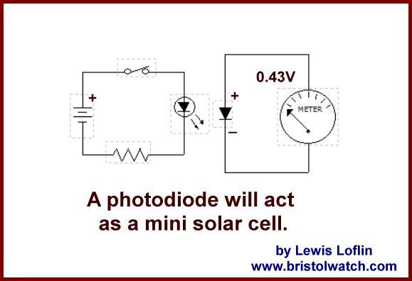
Photodiodes need to be treated in a special way ! 1) use the diode in zero-bias or reverse mode (not in forward mode) 2) when dark, no current flows through the photodiode. 3) a circuit is needed to "catch" the photocurrent and amplify it. Here's an example of such a circuit: This circuit is called a transimpedance amplifier.