depth guide to understanding the alternator IC regulator diagram Circuit Diagram The voltage regulator used in Figure 4 is often called a three terminal fixed voltage regulator. Common output regulated voltages can be 5, 6, 8, 12, 15, 18, 24 volts, etc. (Various current ratings are also available from manufacturers.) Figure 4. Basic voltage regulator circuit diagram. Figure 5. Schematic and connection diagrams for voltage Learn about voltage regulators, electronic circuits that maintain a constant voltage level. Explore the different types of linear and switching regulators, their circuits and how they work.

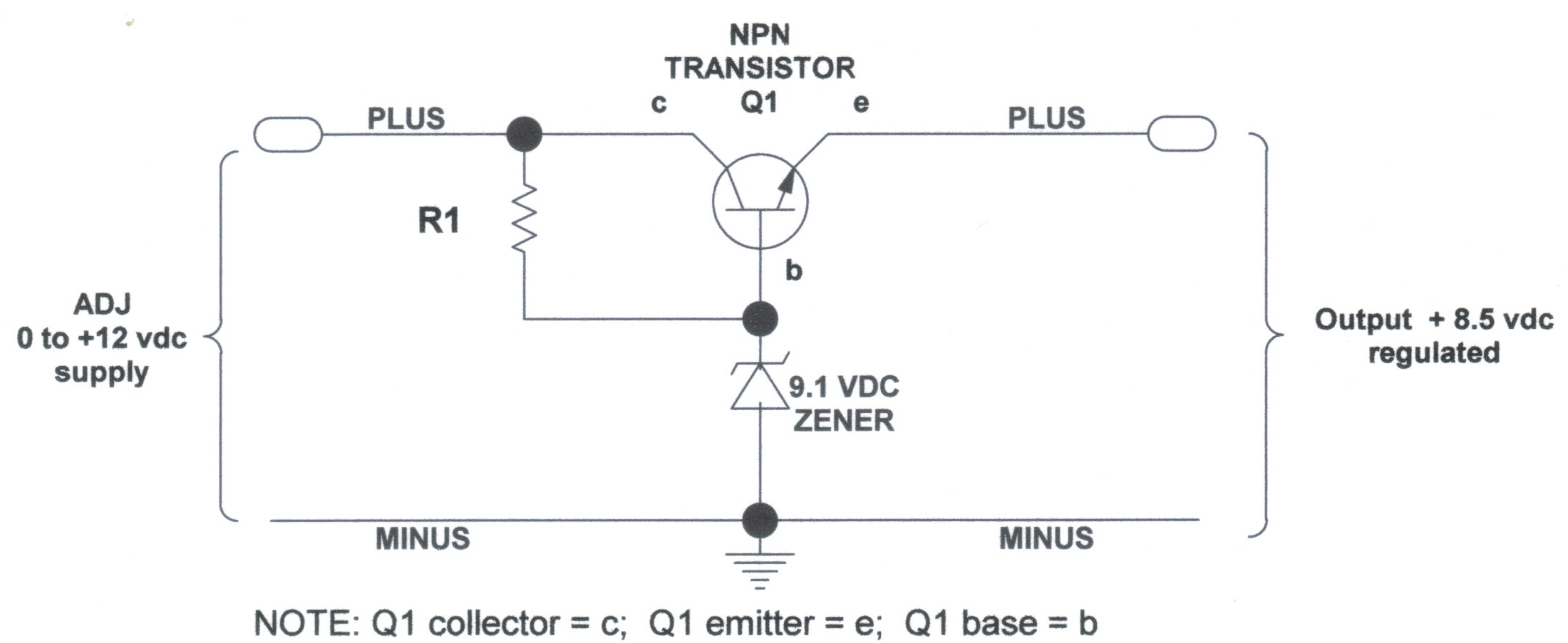
Learn about voltage regulators, their classification, design and applications in power supplies. Find circuit diagrams and explanations of zener controlled transistor voltage regulators, series and shunt types. Find various voltage regulator circuits with schematic diagrams and explanations. Learn how to use different ICs, zener diodes, transformers and other components to regulate voltage levels.
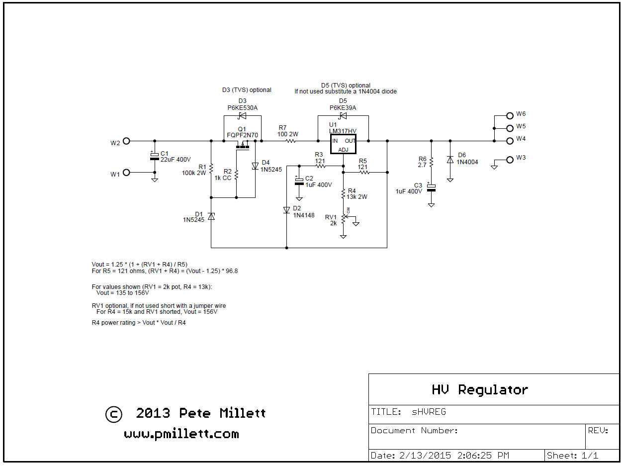
LM317 Voltage Regulator: Pinout, Calculator, and Circuits Circuit Diagram
Components of an Automatic Voltage Regulator Circuit. An automatic voltage regulator circuit consists of several key components that work together to regulate and stabilize the output voltage. These components include: Transformer: The transformer is a key component in the automatic voltage regulator circuit. It is responsible for stepping down Learn how to maintain a constant output voltage level with a voltage regulator circuit diagram. Explore the basic components, functions, and types of voltage regulators, including linear, switching, and programmable regulators. Learn how to create a simple voltage regulator circuit using a schematic diagram. Understand the different types of voltage regulators, their components, and how they work to maintain a constant output voltage.
The LM317 voltage regulator circuit requires only two external resistors to set the output voltage. If a fixed resistor is connected between the output and adjustment pin, it can also be a precision current regulator. Fig 5 : Internal circuit diagram of LM317 with labelled functional blocks. Startup circuit.
