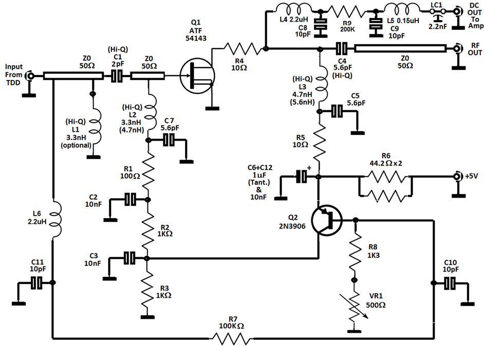
Figure 11 Circuit Diagram Low-Noise Amplifiers Design Specs • Noise Figure: requires very low noise in the input device. For a simple CS stage, the transistor gm must exceed 1/(25 ohms) if the noise figure is to remain below 2 dB. Exercise: calculate the NF if the metal line connecting to the gate has a resistance of Rm. Æ Only one device should dominate NF.

In this tutorial, we will learn the step-by-step guideline of a Low Noise Amplifier (LNA). For this tutorial, we will design an ISM band LNA for 2.4GHz to INA300 / INL300 / INE300 / LEAP Designing a custom IoT product RF Radio / Radio Component Design Antenna Design RF Circuit Design and Measurement Training RF Circuit Design and

Low Noise Amplifier : Circuit, Working, Types & Its Applications Circuit Diagram
But there is more to designing low noise circuits than choosing the lowest voltage noise density (e n) amplifier for a given frequency band. As shown in Figure 2, other noise sources come into play, with incoherent sources combining as a root sum of squares. Figure 2: Op Amp Circuit Noise Sources First, consider resistors as noise sources.
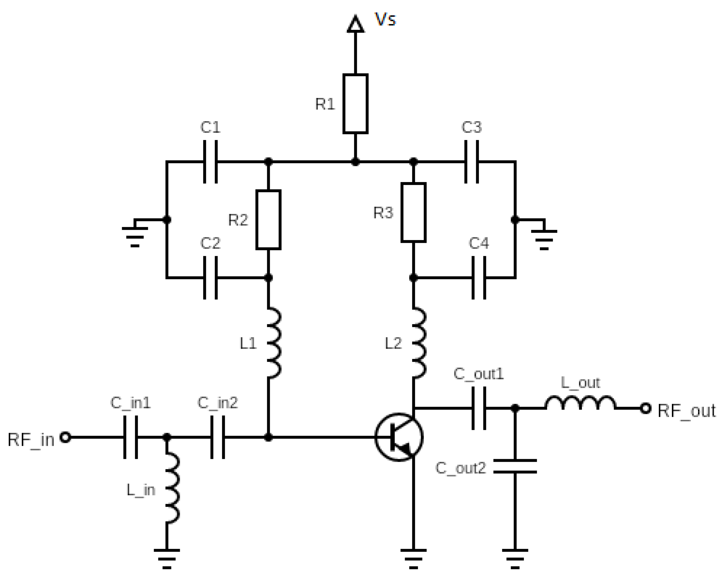
R 1 and C 3 form a simple feedback circuit that helps regulate the operating voltage on C 3. The input voltage, Use the Biased for LNA in your template file as a starting design. The design of the low noise amplifier is explained in the following videos. The basic steps for design are as follows:

Step Guide to Designing a Low Noise Amplifier for ... Circuit Diagram
Low Noise Amplifier Design and Optimization IV.1 CMOS LNA Design and Optimization Overview Low Noise Amplifier (LNA) is the most critical part of a receiver front end, in term of the receiver performance. Many circuits with different configurations have been proposed for LNA, in different applications.
ECE145A/ECE218A Design of Low Noise Amplifiers Set up a biasing circuit such as the one below. Select a large signal device model from the Analog/RF - RF Transistor/Packaged BJT library. Then perform a DC simulation. To see the results of the DC simulation, you go to the Simulate Menu > Annotate DC solution.